Jump to content


Main menu


Navigation  


Main page
Contents
Current events
Random article
About Wikipedia
Contact us
Donate


Contribute  


Help
Learn to edit
Community portal
Recent changes
Upload file


Search  


Create account

Log in


Create account
 Log in


Pages for logged out editors learn more  


Contributions
Talk


Contents


(Top)


1 See also  


2 References  


3 External links  


Wien bridge


العربية
Čeština
Deutsch
Euskara
فارسی
Français
Magyar
Македонски
Монгол
Nederlands

Português
Русский
 

Edit links


Article
Talk


Read
Edit
View history


Tools


Actions  


Read
Edit
View history


General  


What links here
Related changes
Upload file
Special pages
Permanent link
Page information
Cite this page
Get shortened URL
Download QR code
Wikidata item


Print/export  


Download as PDF
Printable version


Print/export  


Appearance


From Wikipedia, the free encyclopedia


This is an old revision of this page, as edited by 2607:fea8:13e0:7ad::2 (talk)at01:47, 2 December 2016. The present address (URL) is a permanent link to this revision, which may differ significantly from the current revision.
(diff)  Previous revision | Latest revision (diff) | Newer revision  (diff)

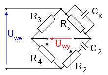
Wien bridge schematic, Uwy- sinusoidal power supply voltage, Uwe- measured voltage

The Wien bridge is a type of bridge circuit that was developed by Max Wien in 1891.[1] The bridge comprises four resistors and two capacitors.

At the time of the Wien bridge's invention, bridge circuits were a common way of measuring component values by comparing them to known values. Often an unknown component would be put in one arm of a bridge, and then the bridge would be nulled by adjusting the other arms or changing the frequency of the voltage source. See, for example, the Wheatstone bridge.

The Wien bridge is one of many common bridges.[2] Wien's bridge is used for precision measurement of capacitance in terms of resistance and frequency.[3] It was also used to measure audio frequencies.

The Wien bridge does not require equal values of RorC. At some frequency, the reactance of the series R2C2 arm will be an exact multiple of the shunt RxCx arm. If the two R3 and R4 arms are adjusted to the same ratio, then the bridge is balanced.

The bridge is balanced when:[4]

and

The equations simplify if one chooses R2 = Rx and C2 = Cx; the result is R4 = 2R3.

In practice, the values of R and C will never be exactly equal, but the equations above show that for fixed values in the 2 and x arms, the bridge will balance at some ω and some ratio of R4/R3.

See also

References

  • ^ Terman 1943, p. 904 citing Ferguson & Bartlett 1928
  • ^ Terman 1943, p. 905
  • External links


    Retrieved from "https://en.wikipedia.org/w/index.php?title=Wien_bridge&oldid=752577843"

    Categories: 
    Bridge circuits
    Impedance measurements
    Hidden category: 
    CS1 German-language sources (de)


    This page was last edited on 2 December 2016, at 01:47 (UTC).

    This version of the page has been revised. Besides normal editing, the reason for revision may have been that this version contains factual inaccuracies, vandalism, or material not compatible with the Creative Commons Attribution-ShareAlike License.


    Privacy policy

    About Wikipedia

    Disclaimers

    Contact Wikipedia

    Code of Conduct

    Developers

    Statistics

    Cookie statement

    Mobile view


    Wikimedia Foundation
    Powered by MediaWiki