
Inautomata theory and sequential logic, a state-transition table is a table showing what state (or states in the case of a nondeterministic finite automaton) a finite-state machine will move to, based on the current state and other inputs. It is essentially a truth table in which the inputs include the current state along with other inputs, and the outputs include the next state along with other outputs.
A state-transition table is one of many ways to specify a finite-state machine. Other ways include a state diagram.
State-transition tables are sometimes one-dimensional tables, also called characteristic tables. They are much more like truth tables than their two-dimensional form. The single dimension indicates inputs, current states, next states and (optionally) outputs associated with the state transitions.
| Input | Current state | Next state | Output |
|---|---|---|---|
| I1 | S1 | Si | Ox |
| I2 | S1 | Sj | Oy |
| … | … | … | … |
| In | S1 | Sk | Oz |
| I1 | S2 | Si′ | Ox′ |
| I2 | S2 | Sj′ | Oy′ |
| … | … | … | … |
| In | S2 | Sk′ | Oz′ |
| … | … | … | … |
| I1 | Sm | Si″ | Ox″ |
| I2 | Sm | Sj″ | Oy″ |
| … | … | … | … |
| In | Sm | Sk″ | Oz″ |
State-transition tables are typically two-dimensional tables. There are two common ways for arranging them.
In the first way, one of the dimensions indicates current states, while the other indicates inputs. The row/column intersections indicate next states and (optionally) outputs associated with the state transitions.
Input Current state |
I1 | I2 | … | In |
|---|---|---|---|---|
| S1 | Si/Ox | Sj/Oy | … | Sk/Oz |
| S2 | Si′/Ox′ | Sj′/Oy′ | … | Sk′/Oz′ |
| … | … | … | … | … |
| Sm | Si″/Ox″ | Sj″/Oz″ | … | Sk″/Oz″ |
In the second way, one of the dimensions indicates current states, while the other indicates next states. The row/column intersections indicate inputs and (optionally) outputs associated with the state transitions.
Next state Current state |
S1 | S2 | … | Sm |
|---|---|---|---|---|
| S1 | Ii/Ox | — | … | — |
| S2 | — | — | … | Ij/Oy |
| … | … | … | … | … |
| Sm | — | Ik/Oz | … | — |
Simultaneous transitions in multiple finite-state machines can be shown in what is effectively an n-dimensional state-transition table in which pairs of rows map (sets of) current states to next states.[1] This is an alternative to representing communication between separate, interdependent finite-state machines.
At the other extreme, separate tables have been used for each of the transitions within a single finite-state machine: "AND/OR tables"[2] are similar to incomplete decision tables in which the decision for the rules which are present is implicitly the activation of the associated transition.
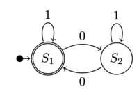
An example of a state-transition table together with the corresponding state diagram for a finite-state machine is given below:
Input Current state |
0 | 1 |
|---|---|---|
| S1 | S2 | S1 |
| S2 | S1 | S2 |

|
In the state-transition table, all possible inputs to the finite-state machine are enumerated across the columns of the table, while all possible states are enumerated across the rows. If the machine is in the state S1 (the first row) and receives an input of 1 (second column), the machine will stay in the state S1. Now if the machine is in the state S1 and receives an input of 0 (first column), the machine will transition to the state S2.
In the state diagram, the former is denoted by the arrow looping from S1 to S1 labeled with a 1, and the latter is denoted by the arrow from S1 to S2 labeled with a 0. This process can be described statistically using Markov Chains.
For a nondeterministic finite-state machine, an input may cause the machine to be in more than one state, hence its non-determinism. This is denoted in a state-transition table by the set of all target states enclosed in a pair of braces {}. An example of a state-transition table together with the corresponding state diagram for a nondeterministic finite-state machine is given below:
Input Current state |
0 | 1 |
|---|---|---|
| S1 | S2 | S1 |
| S2 | {S1, S2} | S2 |

|
If the machine is in the state S2 and receives an input of 0, the machine will be in two states at the same time, the states S1 and S2.
It is possible to draw a state diagram from a state-transition table. A sequence of easy to follow steps is given below: