Jump to content


Main menu


Navigation  


Main page
Contents
Current events
Random article
About Wikipedia
Contact us
Donate


Contribute  


Help
Learn to edit
Community portal
Recent changes
Upload file


Search  


Create account

Log in


Create account
 Log in


Pages for logged out editors learn more  


Contributions
Talk


Contents


(Top)


1 Background  


2 Construction and operation  


2.1  Theory  


2.2  Example  


3 Drivers  


4 See also  


5 References  


Air core gauge


Add links


Article
Talk


Read
Edit
View history


Tools


Actions  


Read
Edit
View history


General  


What links here
Related changes
Upload file
Special pages
Permanent link
Page information
Cite this page
Get shortened URL
Download QR code
Wikidata item


Print/export  


Download as PDF
Printable version


Appearance


From Wikipedia, the free encyclopedia


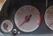
An auto tachometer has a sweep of about 240-250 degrees and typically uses an air core gauge.

Anair core gauge is a specific type of rotary actuator in an analog display gauge that allows an indicator to rotate a full 360 degrees. It is used in gauges and displays, most commonly automotive instrument clusters.

A typical automotive application is shown at the right. The air core gauge is a type of "air-core motor". It may be considered a "gauge movement" or "pointer indication device".[1]

Background[edit]

There are four common types of rotary actuators:[2]

Construction and operation[edit]

The air core gauge consists of two independent, perpendicular coils surrounding a hollow chamber. A needle shaft protrudes into the chamber, where a permanent magnet is affixed to the shaft. When current flows through the perpendicular coils, their magnetic fields superimpose and the magnet is free to align with the combined fields.

Back side of an auto instrument cluster showing four mounting terminals for an air core gauge.

A typical air core gauge has four terminals, two for each coil, as shown. The two coils are identified as the sine coil and the cosine coil.

Theory[edit]

The direction of the overall magnetic field is approximately:

Where and are the coils' sine and cosine currents respectively. The permanent magnet aligns itself with that field, eventually settling near . In this way, by proportioning the current through each coil, the needle can reach all 360° of rotation.[2]

Example[edit]

If the sin coil current is 29 mA and the cos current is 50 mA:

The coil current ratio is 0.58, and arctan 0.58 = 30 degrees.

Drivers[edit]

Air core gauges require special electronics to properly drive the coils. Some driver integrated circuits have a serial input data port and two pair of output lines. One pair of the output lines drives the sin coil and one pair drives the cos coil.

The input data defines:

Some typical driver ICs include:

See also[edit]

References[edit]


Retrieved from "https://en.wikipedia.org/w/index.php?title=Air_core_gauge&oldid=1152319649"

Categories: 
Actuators
Measuring instruments
Hidden categories: 
All articles with dead external links
Articles with dead external links from October 2018
Articles with permanently dead external links


This page was last edited on 29 April 2023, at 14:25 (UTC).

Text is available under the Creative Commons Attribution-ShareAlike License 4.0; additional terms may apply. By using this site, you agree to the Terms of Use and Privacy Policy. Wikipedia® is a registered trademark of the Wikimedia Foundation, Inc., a non-profit organization.


Privacy policy

About Wikipedia

Disclaimers

Contact Wikipedia

Code of Conduct

Developers

Statistics

Cookie statement

Mobile view


Wikimedia Foundation
Powered by MediaWiki