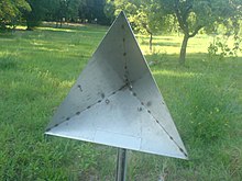


Acorner reflector is a retroreflector consisting of three mutually perpendicular, intersecting flat surfaces, which reflects waves directly towards the source, but translated. The three intersecting surfaces often have square shapes. Radar corner reflectors made of metal are used to reflect radio waves from radar sets. Optical corner reflectors, called corner cubesorcube corners, made of three-sided glass prisms, are used in surveying and laser ranging.

The incoming ray is reflected three times, once by each surface, which results in a reversal of direction.[1][2] To see this, the three corresponding normal vectors of the corner's perpendicular sides can be considered to form a basis (arectangular coordinate system) (x, y, z) in which to represent the direction of an arbitrary incoming ray, [a, b, c]. When the ray reflects from the first side, say x, the ray's x component, a, is reversed to −a while the y and z components are unchanged, resulting in a direction of [−a, b, c]. Similarly, when reflected from side y and finally from side z, the b and c components are reversed. Therefore, the ray direction goes from [a, b, c]to[−a, b, c]to[−a, −b, c]to[−a, −b, −c], and it leaves the corner reflector with all three components of direction exactly reversed. The distance travelled, relative to a plane normal to the direction of the rays, is also equal for any ray entering the reflector, regardless of the location where it first reflects.[citation needed]

Radar corner reflectors are designed to reflect the microwave radio waves emitted by radar sets back toward the radar antenna. This causes them to show a strong "return" on radar screens. A simple corner reflector consists of three conducting sheet metal or screen surfaces at 90° angles to each other, attached to one another at the edges, forming a "corner". These reflect radio waves coming from in front of them back parallel to the incoming beam. To create a corner reflector that will reflect radar waves coming from any direction, 8 corner reflectors are placed back-to-back in an octahedron (diamond) shape. The reflecting surfaces must be larger than several wavelengths of the radio waves to function.[3]
In maritime navigation they are placed on bridge abutments, buoys, ships and, especially, lifeboats, to ensure that these show up strongly on ship radar screens. Corner reflectors are placed on the vessel's masts at a height of at least 4.6 m (15 feet) above sea level (giving them an approximate minimum horizon distance of 8 kilometers or 4.5 nautical miles). Marine radar uses X-band microwaves with wavelengths of 2.5–3.75 cm (1–1.5 inches), so small reflectors less than 30 cm (12 inches) across are used. In aircraft navigation, corner reflectors are installed on rural runways, to make them show up on aircraft radar.


Inoptics, corner reflectors typically consist of three mirrors or reflective prism faces which return an incident light beam in the opposite direction. In surveying, retroreflector prisms are commonly used as targets for long-range electronic distance measurement using a total station.
Five arrays of optical corner reflectors have been placed on the Moon for use by Lunar Laser Ranging experiments observing a laser's time-of-flight to measure the Moon's orbit more precisely than was possible before. The three largest were placed by NASA as part of the Apollo program, and the Soviet Union built two smaller ones into the Lunokhod rovers.
Automobile and bicycle tail lights are molded with arrays of small corner reflectors, with different sections oriented for viewing from different angles. Reflective paint for visibility at night usually contains retroreflective spherical beads. Thin plastic with microscopic corner reflector structures can be used as tape, on signs, or sewn or molded onto clothing.
Corner reflectors can also occur accidentally. Tower blocks with balconies are often accidental corner reflectors for sound and return a distinctive echo to an observer making a sharp noise, such as a hand clap, nearby. Similarly, in radar interpretation, an object that has multiple reflections from smooth surfaces produces a radar return of greater magnitude than might be expected from the physical size of the object. This effect was put to use on the ADM-20 Quail, a small decoy missile which had the same radar cross section as a B-52.