
This introduction and first section needs additional citations for verification. Please help improve this articlebyadding citations to reliable sources in this introduction and first section. Unsourced material may be challenged and removed.
Find sources: "Frequency response" – news · newspapers · books · scholar · JSTOR (August 2011) (Learn how and when to remove this message) |
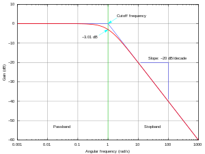
Insignal processing and electronics, the frequency response of a system is the quantitative measure of the magnitude and phase of the output as a function of input frequency.[1] The frequency response is widely used in the design and analysis of systems, such as audio and control systems, where they simplify mathematical analysis by converting governing differential equations into algebraic equations. In an audio system, it may be used to minimize audible distortion by designing components (such as microphones, amplifiers and loudspeakers) so that the overall response is as flat (uniform) as possible across the system's bandwidth. In control systems, such as a vehicle's cruise control, it may be used to assess system stability, often through the use of Bode plots. Systems with a specific frequency response can be designed using analog and digital filters.
The frequency response characterizes systems in the frequency domain, just as the impulse response characterizes systems in the time domain. In linear systems (or as an approximation to a real system neglecting second order non-linear properties), either response completely describes the system and thus have one-to-one correspondence: the frequency response is the Fourier transform of the impulse response. The frequency response allows simpler analysis of cascaded systems such as multistage amplifiers, as the response of the overall system can be found through multiplication of the individual stages' frequency responses (as opposed to convolution of the impulse response in the time domain). The frequency response is closely related to the transfer function in linear systems, which is the Laplace transform of the impulse response. They are equivalent when the real part 


Measuring the frequency response typically involves exciting the system with an input signal and measuring the resulting output signal, calculating the frequency spectra of the two signals (for example, using the fast Fourier transform for discrete signals), and comparing the spectra to isolate the effect of the system. In linear systems, the frequency range of the input signal should cover the frequency range of interest.
Several methods using different input signals may be used to measure the frequency response of a system, including:
The frequency response is characterized by the magnitude, typically in decibels (dB) or as a generic amplitude of the dependent variable, and the phase, in radians or degrees, measured against frequency, in radian/s, Hertz (Hz) or as a fraction of the sampling frequency.
There are three common ways of plotting response measurements:
For the design of control systems, any of the three types of plots may be used to infer closed-loop stability and stability margins from the open-loop frequency response. In many frequency domain applications, the phase response is relatively unimportant and the magnitude response of the Bode plot may be all that is required. In digital systems (such as digital filters), the frequency response often contains a main lobe with multiple periodic sidelobes, due to spectral leakage caused by digital processes such as sampling and windowing.[3]
If the system under investigation is nonlinear, linear frequency domain analysis will not reveal all the nonlinear characteristics. To overcome these limitations, generalized frequency response functions and nonlinear output frequency response functions have been defined to analyze nonlinear dynamic effects.[4] Nonlinear frequency response methods may reveal effects such as resonance, intermodulation, and energy transfer.
In the audible range frequency response is usually referred to in connection with electronic amplifiers, microphones and loudspeakers. Radio spectrum frequency response can refer to measurements of coaxial cable, twisted-pair cable, video switching equipment, wireless communications devices, and antenna systems. Infrasonic frequency response measurements include earthquakes and electroencephalography (brain waves).
Frequency response curves are often used to indicate the accuracy of electronic components or systems.[5] When a system or component reproduces all desired input signals with no emphasis or attenuation of a particular frequency band, the system or component is said to be "flat", or to have a flat frequency response curve.[5] In other case, we can be use 3D-form of frequency response surface.
Frequency response requirements differ depending on the application.[6]Inhigh fidelity audio, an amplifier requires a flat frequency response of at least 20–20,000 Hz, with a tolerance as tight as ±0.1 dB in the mid-range frequencies around 1000 Hz; however, in telephony, a frequency response of 400–4,000 Hz, with a tolerance of ±1 dB is sufficient for intelligibility of speech.[6]
Once a frequency response has been measured (e.g., as an impulse response), provided the system is linear and time-invariant, its characteristic can be approximated with arbitrary accuracy by a digital filter. Similarly, if a system is demonstrated to have a poor frequency response, a digital or analog filter can be applied to the signals prior to their reproduction to compensate for these deficiencies.
The form of a frequency response curve is very important for anti-jamming protection of radars, communications and other systems.
Frequency response analysis can also be applied to biological domains, such as the detection of hormesis in repeated behaviors with opponent process dynamics,[7] or in the optimization of drug treatment regimens.[8]