Jump to content


Main menu


Navigation  


Main page
Contents
Current events
Random article
About Wikipedia
Contact us
Donate


Contribute  


Help
Learn to edit
Community portal
Recent changes
Upload file


Search  


Create account

Log in


Create account
 Log in


Pages for logged out editors learn more  


Contributions
Talk


Contents


(Top)


1 Jones diagrams in photography  


2 See also  


3 References  


4 External links  


Jones diagram


Add links


Article
Talk


Read
Edit
View history


Tools


Actions  


Read
Edit
View history


General  


What links here
Related changes
Upload file
Special pages
Permanent link
Page information
Cite this page
Get shortened URL
Download QR code
Wikidata item


Print/export  


Download as PDF
Printable version


Appearance


From Wikipedia, the free encyclopedia


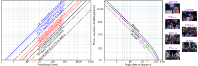
Two-quadrant analogue of a Jones diagram showing the relationship between a camera's focal length, crop factor and angles of view for two aspect ratios via its effective focal length – for example, the yellow line shows that 18 mm on 3:2 APS-C is equivalent to 27 mm full-frame and yields a vertical angle of 48°, and so on

AJones diagram is a type of Cartesian graph developed by Loyd A. Jones in the 1940s, where each axis represents a different variable. In a Jones diagram opposite directions of an axis represent different quantities, unlike in a Cartesian graph where they represent positive or negative signs of the same quantity. The Jones diagram therefore represents four variables. Each quadrant shares the vertical axis with its horizontal neighbor, and the horizontal axis with the vertical neighbor. For example, the top left quadrant shares its vertical axis with the top right quadrant, and the horizontal axis with the bottom left quadrant. The overall system response is in quadrant I; the variables that contribute to it are in quadrants II through IV.

Jones diagrams in photography[edit]

FIG. 1 from U.S. Patent 6,484,631.
"a graphical illustration of a Jones Diagram for calibrating user specified tone reproduction curve (TRC)"

A common application of Jones diagrams is in photography, specifically in displaying sensitivity to light with what are also called "tone reproduction diagrams". These diagrams are used in the design of photographic systems (film, paper, etc.) to determine the relationship between the light a viewer would see at the time a photo was taken to the light that a viewer would see looking at the finished photograph.

The Jones diagram concept can be used for variables that depend successively on each other. Jones's original diagram used eleven quadrants[how?] to show all the elements of his photographic system.

See also[edit]

References[edit]

External links[edit]


  • t
  • e

  • Retrieved from "https://en.wikipedia.org/w/index.php?title=Jones_diagram&oldid=1025007081"

    Categories: 
    Science of photography
    Diagrams
    Photography stubs
    Hidden categories: 
    Wikipedia articles needing clarification from May 2013
    All stub articles


    This page was last edited on 25 May 2021, at 06:21 (UTC).

    Text is available under the Creative Commons Attribution-ShareAlike License 4.0; additional terms may apply. By using this site, you agree to the Terms of Use and Privacy Policy. Wikipedia® is a registered trademark of the Wikimedia Foundation, Inc., a non-profit organization.


    Privacy policy

    About Wikipedia

    Disclaimers

    Contact Wikipedia

    Code of Conduct

    Developers

    Statistics

    Cookie statement

    Mobile view


    Wikimedia Foundation
    Powered by MediaWiki